

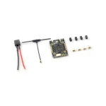
Happymodel CruxF405HD ELRS AIO 3in1 Flight Controller for Digital HD Toothpick FPV Drone
Stok 11
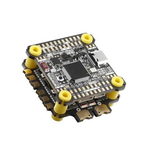
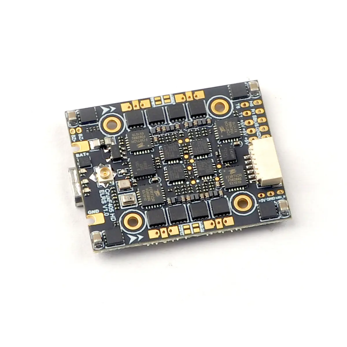
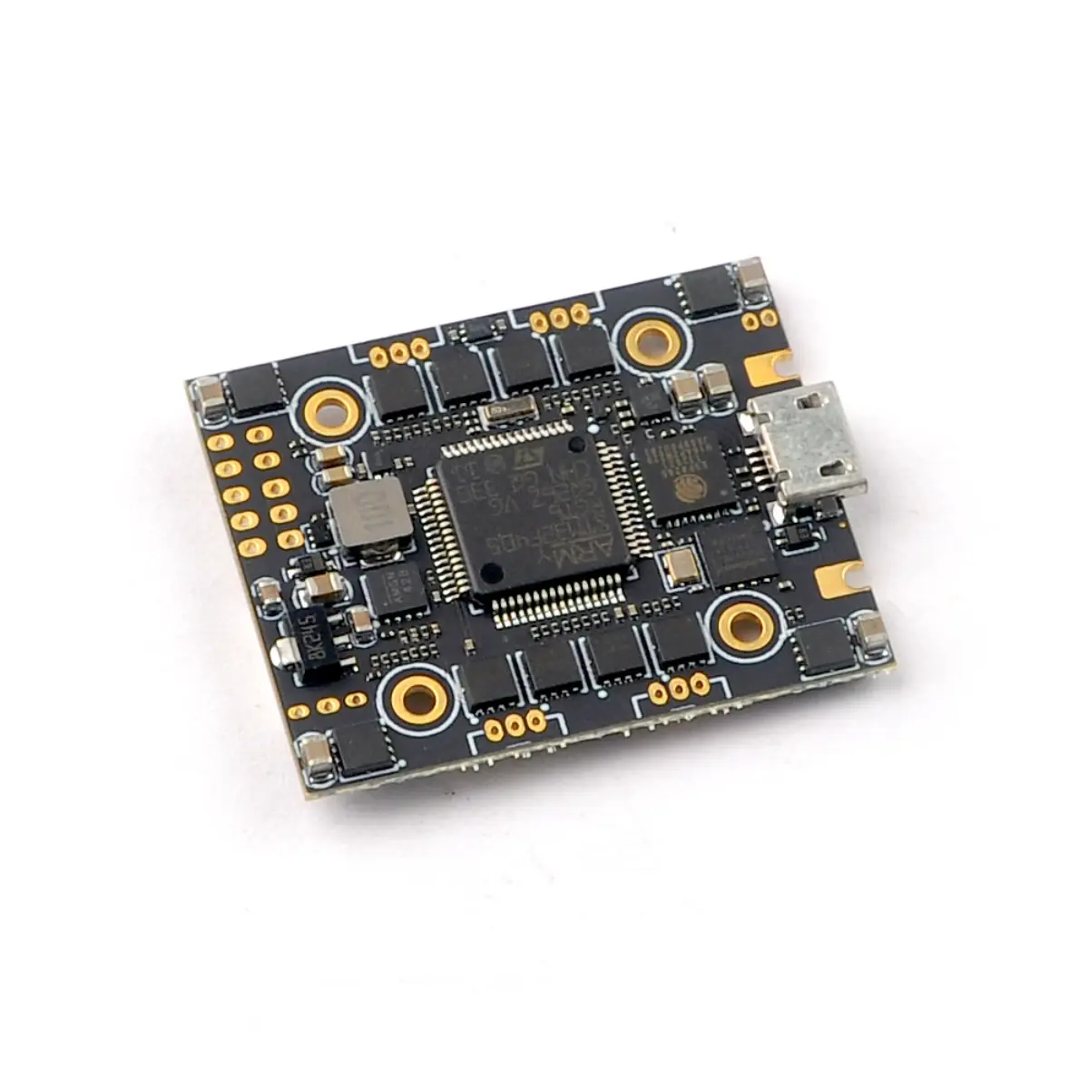
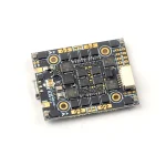
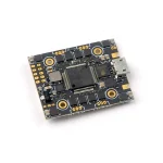
The CruxF405HD ELRS AIO flight controller comes with integrated UART 2.4GHz ExpressLRS receiver and 20A Blheli_s ESC(Bluejay firmware pre-installed) which could support 3-4s battery. Bigger Mosfet could support high to 20A currents would be better for 3-4S toothpick drone or long range FPV drone. Reserved 6 pin socket for DJI HD equipment plug and play. It’s a great solution of build HD digital FPV drone .
Specifications:
Flight controller
MCU: STM32F405RGT6 (168MHZ, 1Mbyte FLASH)
GYRO Sensor: ICM42688 (SPI connection)
Mount hole size: 20mm*20mm
Power supply: 3~4S battery input (DC 11V-17.4V)
Built-in 20A(each) Blheli_S 4in1 ESC
Built-in Serial ExpressLRS 2.4G (Default connected to UART2)
Built-in BMP280 Barometer
Built-in 8MBp blackbox
Built-in voltage meter sensor , voltage meter scale 110
Built-in current meter sensor , current meter scale 470
Flight controller firmware target: BETAFLIGHTF4
Onboard 4in1 ESC
MCU upgraded to EFM8BB21
Power supply: 3-4S LiPo/LiPo HV (11v/17v)
Currents: 20A continuous peak 25A (5 seconds)
Support BLHeliSuite programmable
Factory firmware: Bluejay 0.19.2
Firmware target: F_H_40_48_v0.19.2
Default protocol: DSHOT150/DSHOT300/DSHOT600
Onboard UART ExpressLRS 2.4GHz Receiver
Packet Rate option: 25Hz/50Hz/150Hz/250Hz/500Hz
RF Frequency: 2.4GHz
Antenna plug: IPEX
Telemetry output Power: <12dBm
Receiver protocol: CRSF
Default firmware version: ExpressLRS V3.0.1
Onboard voltage and Amperage meters settings
Voltage meter scale setting 110
Amperage meter scale setting 470
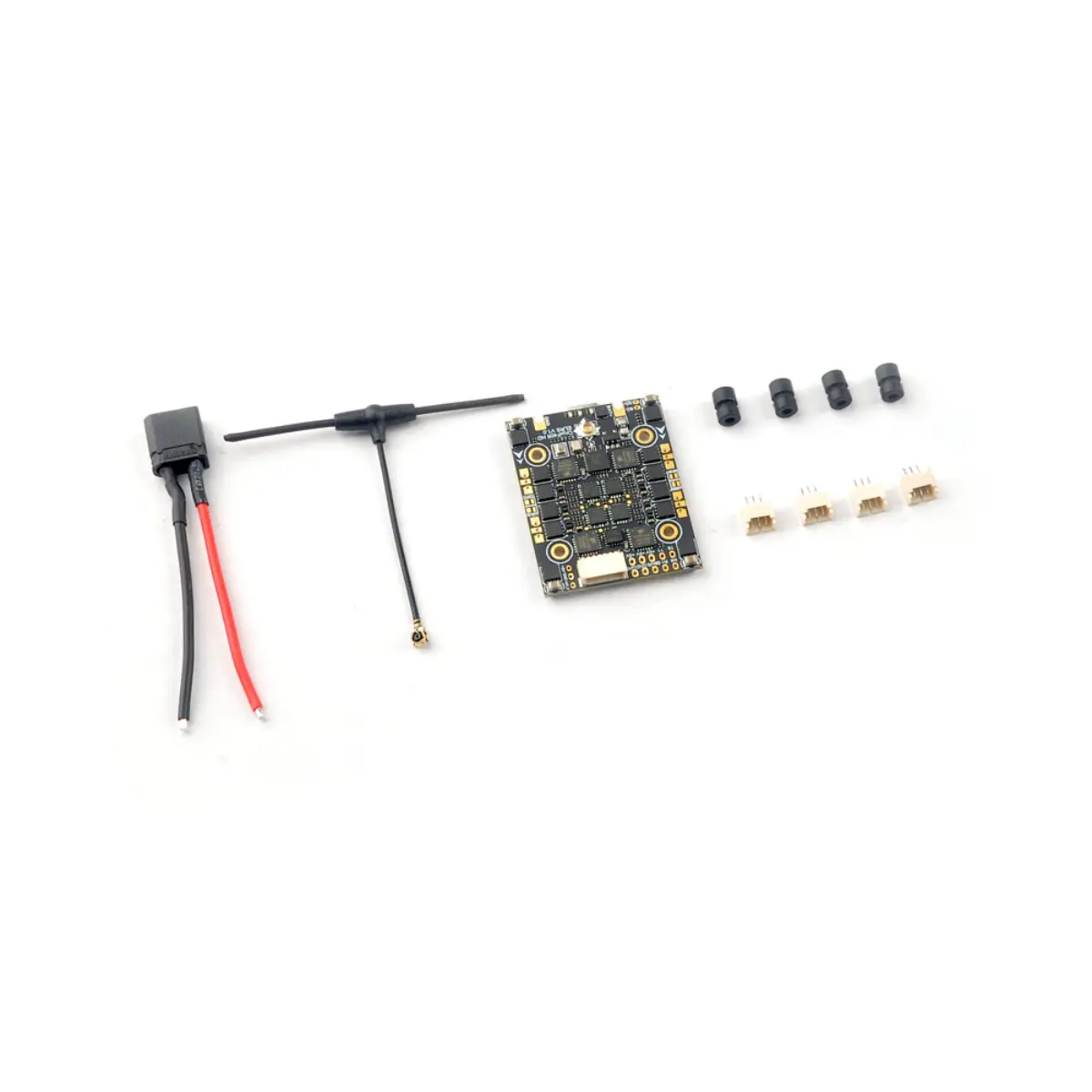
Includes:
1x CruxF405HD FC
4x Motor sockets
4x Dampers
1x Antenna
1x XT30 battery cable
Binding procedure:
1. Supply power to the flight controller by plug USB, wait until the red LED on the FC is off, immediately turn off the power, and then repeat again the above steps. When the FC is powered on for the third time, the red LED light will start to double-flash, which means that the Receiver enters the binding mode
2. Please make sure your ExpressLRS tx module firmware is v3.x.x. And go to ExpressLRS.lua from “TOOLS” menu of your radio transmitter. Then hit [Bind] to binding with the onboard ExpressLRS receiver. The red LED should blinking slowly first then turn to solid, that means binding was successfully. If the red led keep tri-flash after binding ,please change Model Match tab value from “off” to “on” or from “on” to “off”
Receiver LED status meanings:
Red LED solid means bind successful or RC link established; Red LED double-flash means get into bind mode; Red LED flash slowly means no RC signal input from TX module; Red LED continuous flash fast means ExpressLRS wifi enabled; Red LED tri-flash means model mismatch need to change model match from “off” to “on”.
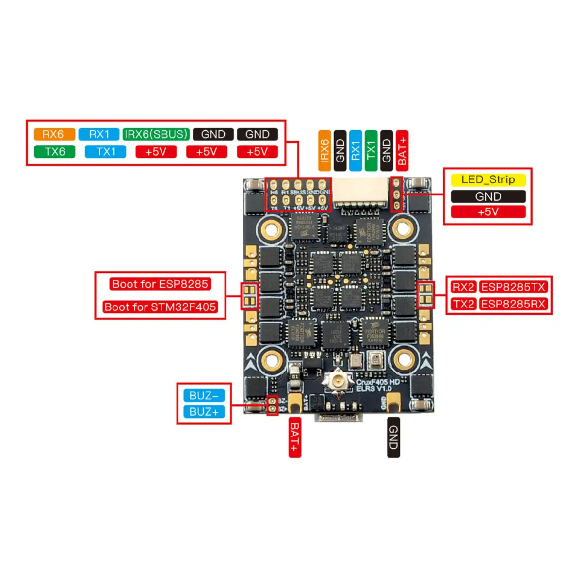
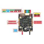
UART description:
ELRS receiver was connected to UART2 default out of factory.
Usually UART1 or UART6 Could be used for MSP OSD with HD VTX.
UART6 could be used for GPS or other serial equipment.
IRX6 is an inverted serial RX6 for SBUS input.
IRX6 and TX6/RX6 couldn’t be used at the same time.
| Berat | 0,2 kg |
|---|
Hanya pelanggan yang sudah login dan telah membeli produk ini yang dapat memberikan ulasan.
Cek Ongkir
Setiap pesanan dikemas dengan aman untuk membantu menjaga produk selama proses pengiriman. Kami menawarkan produk original dengan harga yang kompetitif dan layanan terbaik. Pilihan metode pengiriman yang tersedia akan ditampilkan saat checkout sesuai dengan produk dan alamat tujuan.
Kami berkomitmen menyediakan produk original dan layanan terbaik. Apabila produk yang Anda terima tidak sesuai atau mengalami kerusakan saat diterima (DOA), silakan hubungi Customer Support maksimal 48 jam setelah paket diterima. Pengembalian barang, pengembalian dana, dan garansi mengikuti Kebijakan Pengembalian Dana dan Barang yang berlaku.
Read MoreProduk Terkait
-
SpeedyBee F405 AIO V2 35/40A Bluejay 25.5×25.5 3-6S Flight Controller
Rp1.185.000 -
JHEMCU GSF405A AIO F405 Flight Controller FC 5A ELRS 2.4G 25x25mm
About this product The JHEMCU GS405A AIO features an F4 FC and a 5A ESC with built-in ELRS 2.4GHz receiver. This is an ultra-light 3.3g brushless AIO flight controller with 25.5×25.5mm mounting pattern!! This FC can handle 5A of continuous current and up to 2S. This AIO also features a built-in 8MB blackbox, buzzer interface, and camera interface. GSF405A AIO […]Rp790.000 -
JHEMCU GHF722 HD AIO Flight Controller 40A 2-6S ESC 25x25mm
Specifications Model: GHF722AIO-HD ESC-40A Item Name: JHEMCU GHF722AIO- HD 40A F722 Flight Controller STM32F722 W/5V 10V BEC Gebaut-in 40A BLHELI_S 2-6S 4in1 ESC for FPV Racing Drone Dimensions: 33.5mm x 33.5mm CPU: STM32F722 Mounting Hole: 25.5×25.5mm Weight: 7.8g Gyro: ICM USB: MicroUSB and Included TYPE-C w/ Adapter Board Firmware: JHEF7DUAL, Betaflight 4.3.0+ Required Black box: 16MB ESC Specifications Con. Current: 40A Burst Current: 50A […]Rp1.055.000 -
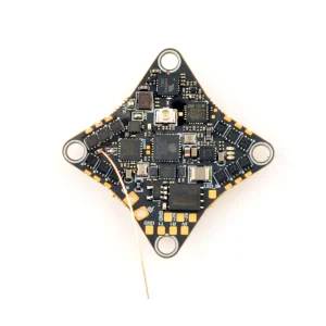
Happymodel CrazybeeG473 V1.0 AIO 5-IN-1 ELRS Flight Controller
This the first AIO 5-IN-1 flight controller based on G473 MCU platform from Happymodel, Built-in UART ExpressLRS receiver and OpenVTXbetter for 65mm 1s Micro FPV whoops. FC MCU: STM32G473CEU6 Gyro: ICM42688P or LSM6DSV16X Blackbox memory: 16MB Sensor: Voltage & Current BEC: 5V, Max. 2A UART: UART 1, UART 2, UART 3 (For RX), UART 4(For […]Rp950.000 -
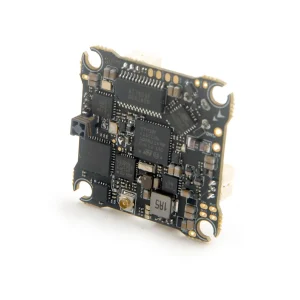
Happymodel X12 ELRS V2.1 AIO 5-IN-1 Flight Controller
The world first 5-IN-1 AIO flight controller, OPENVTX(up to 400mw), 12A Brushless Blheli_S ESC and Betaflight OSD coming out recently. It comes with onboard SPI ELRS receiver which support ELRS TX module 2.x firmware, and also provide other receiver option like SPI Frsky receiver which support Frsky D8/D16 , REDPINE and SFHSS. This is an […]Rp950.000 -
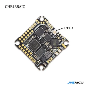
JHEMCU GHF435AIO V2 Flight Controller 2-4S 20A ESC with 2.4G ELRS (UFL/IPEX) 25x25mm
JHEMCU GHF435AIO V2 20A F435 2-4S Flight Controller Built-in 5V BEC Specification Value Model GHF435AIO V2 MCU AT32F435CG (288MHz) IMU ICM-42688-P (Gyro/Accelerometer) OSD AT7456E Barometer Yes Blackbox 16MB Input Voltage 2–4S (7.4V–17V) 5V BEC 5V / 2.5A (±0.1V) UART UART1, UART2, UART3, UART5 Receiver Support ELRS (CRSF), TBS (CRSF), SBUS, IBUS LED Strip WS2812 […]Rp935.000
Belum ada ulasan.